Crane collision prevention system using CLAS
Introduction
We have developed a collision prevention system for cranes used at construction sites in cooperation with SC Machinery Corp..
This system uses the CLAS (Centimeter Class Positioning Augmentation Service) of MICHIBIKI, the Japanese version of GPS, to acquire the crane's position and orientation in real time and alert the crane operator of the danger of a collision.
In this issue, we will introduce you to this CLAS-based crane collision prevention system.
GNSS is mounted on the top and bottom of the crane
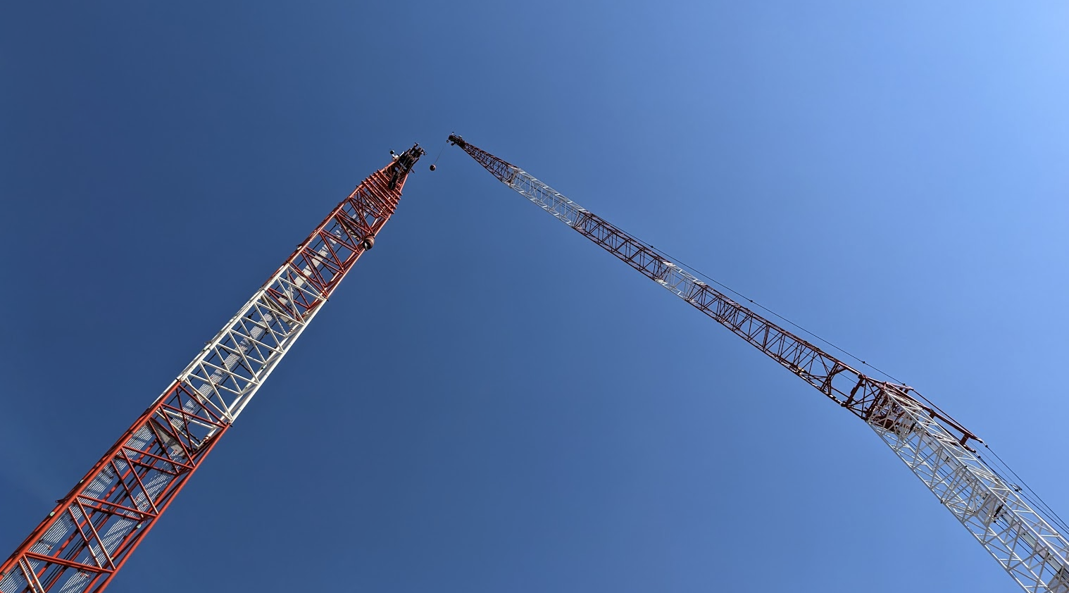
The cranes targeted by this system are called crawler cranes or tower cranes.
The arm used to lift the load is called a jib.
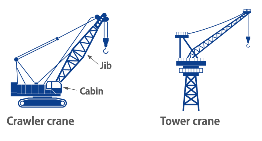
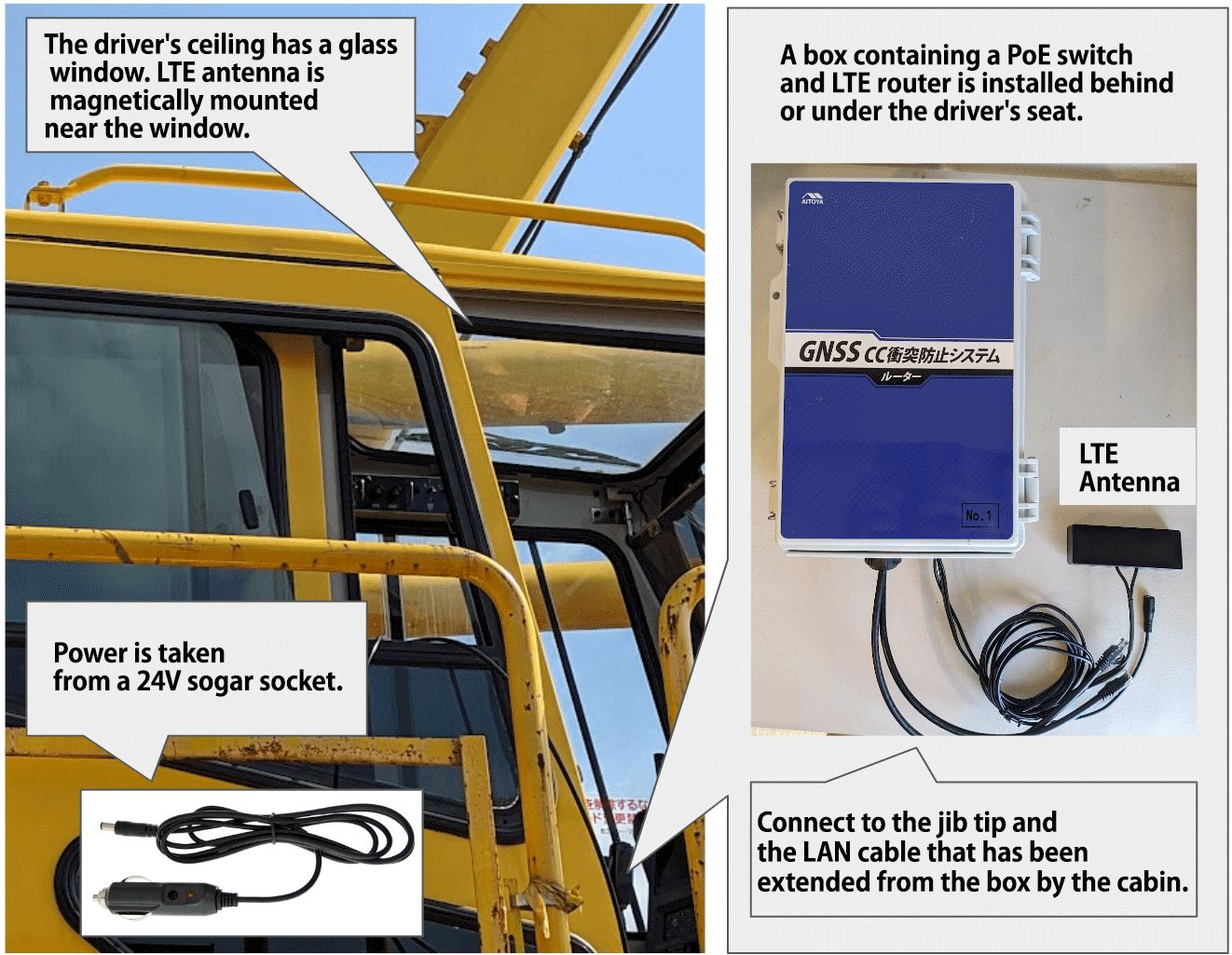
At the end of this jib, a GNSS antenna and a receiver placed inside a waterproof box are attached.
The receiver is a Mosaic-CLAS from Septentrio.
In addition to the receiver, the waterproof box contains a microcontroller (Raspberry Pi) to control the receiver.
The antenna is a helical antenna (Tallysman HC976), used in conjunction with a mechanism that allows the antenna to always point vertically upward, regardless of the angle of the jib.
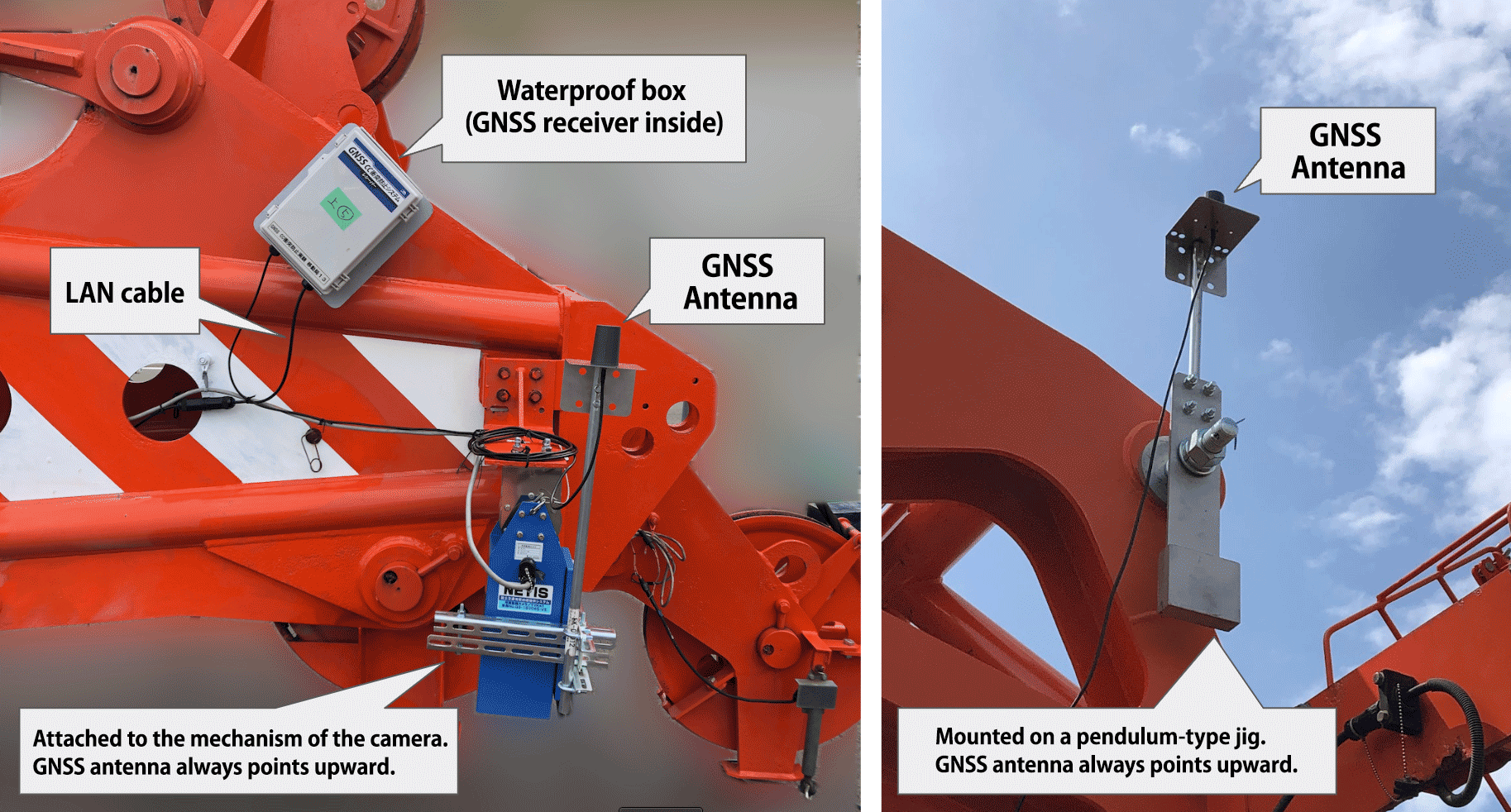
Similarly, a GNSS antenna and receiver in a waterproof box are mounted beside the driver's seat (called the cabin) where the operator sits.
We want to use GNSS to measure the tip of the jib and the working radius of the jib, but we cannot mount the antenna at the very tip of the jib or at the center of the swing. Therefore, we measure the offset from the tip of the jib and the swivel center to the actual position where the antenna is mounted with a tape measure. (We only measure the horizontal offset.)
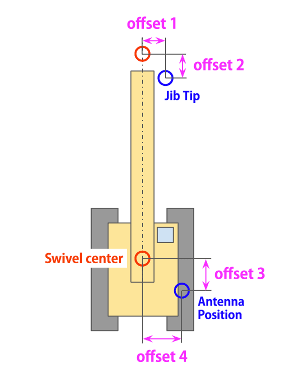
From the measured GNSS antenna position, the above offset is corrected to calculate the position of the jib tip and the center of turn.
The GNSS receivers mounted at the jib tip and on the side of the cabin need a power supply and a communication path to receive the measured values.
PoE LAN is used for this purpose.
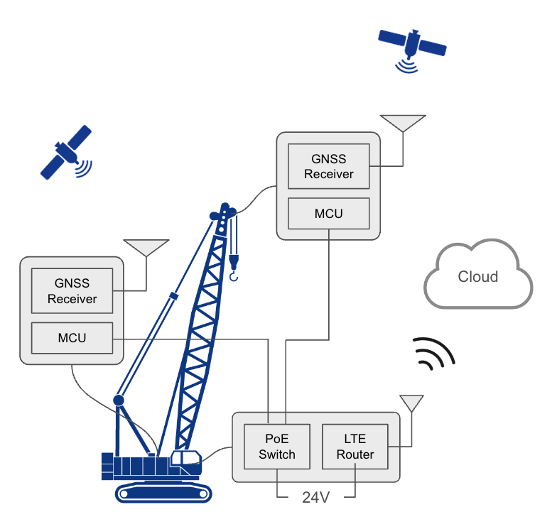
LAN cables are run from the jib tip and from the receiver box by the cabin and are connected to the PoE switch located inside the cabin. The PoE switch is housed in a plastic box with the LTE router, which is located in the cabin.
The above equipment is installed on all cranes to be targeted, and the position of each antenna is measured by CLAS positioning.
Measurements are taken at a frequency of 5 times per second (5 Hz). The measured data (NMEA data) is transferred to a server in the cloud for subsequent processing.
Measure the distance from your aircraft to the nearest other aircraft
The distance from the tip of the jib of one crane to the jib of another crane is calculated, and the distance to the nearest other crane is determined.
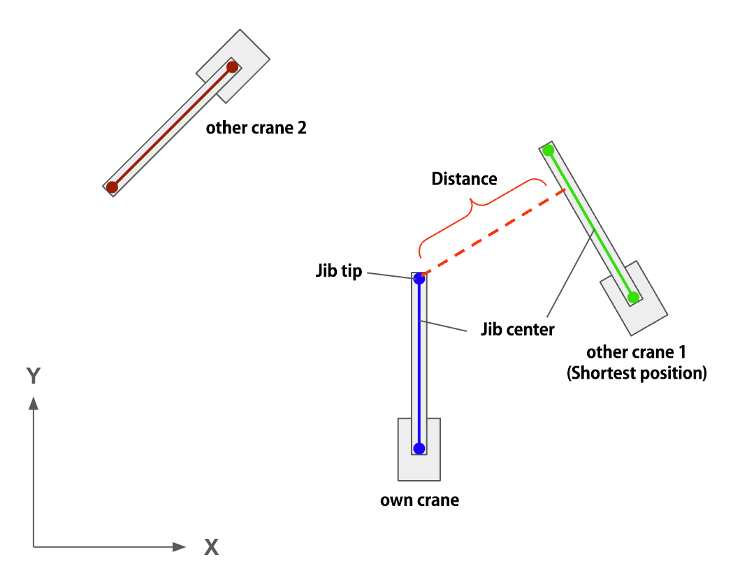
GNSS can measure the horizontal position (X, Y) and height (Z) of each antenna, of which only the horizontal position is used.
Alerts the operator when it falls below a predetermined distance
An iPad is installed in the cabin, and on the browser screen of the iPad, the position of the other aircraft relative to the own aircraft, the direction of the jib, and the distance to the other aircraft at the shortest position are calculated and updated every 0.2 seconds.
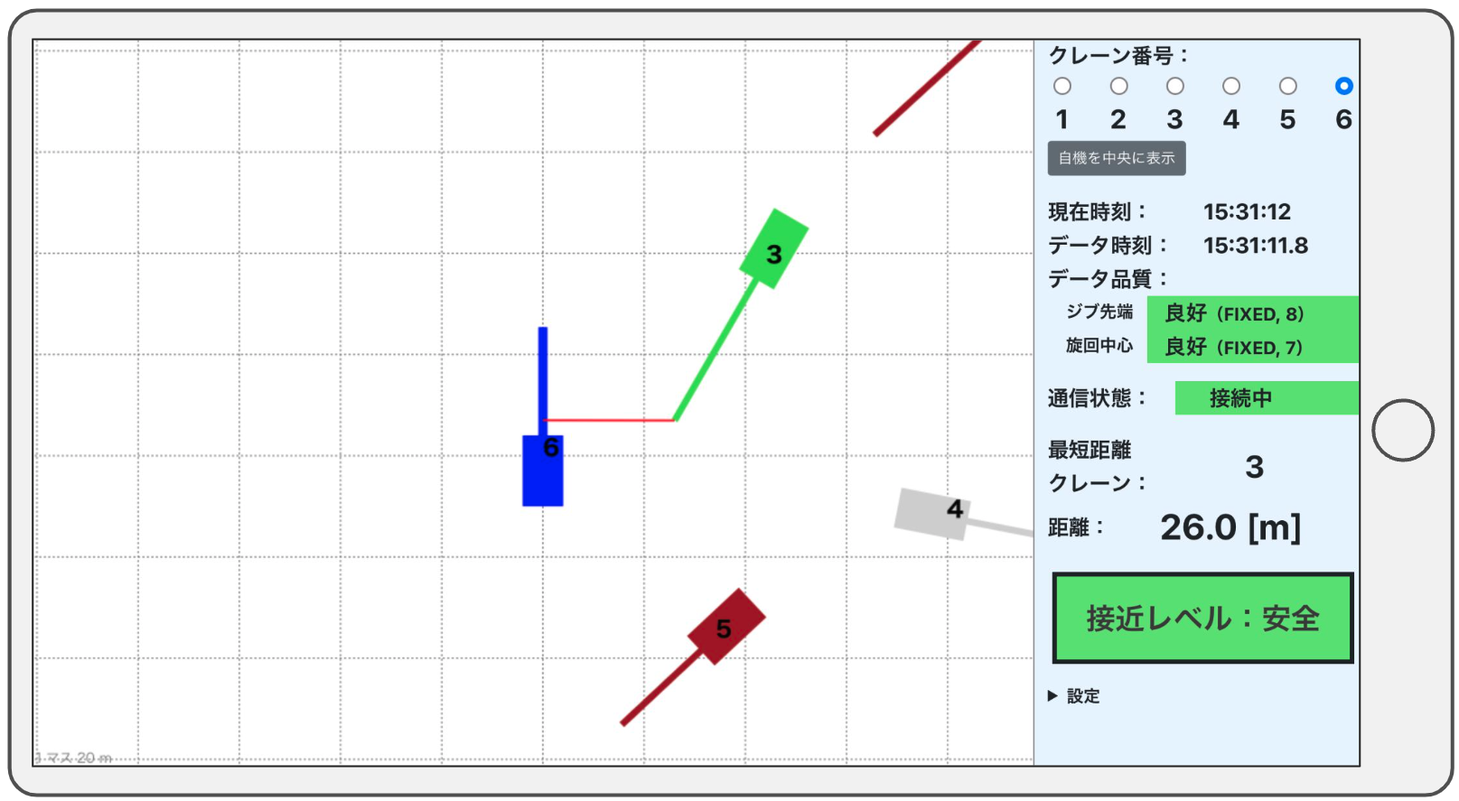
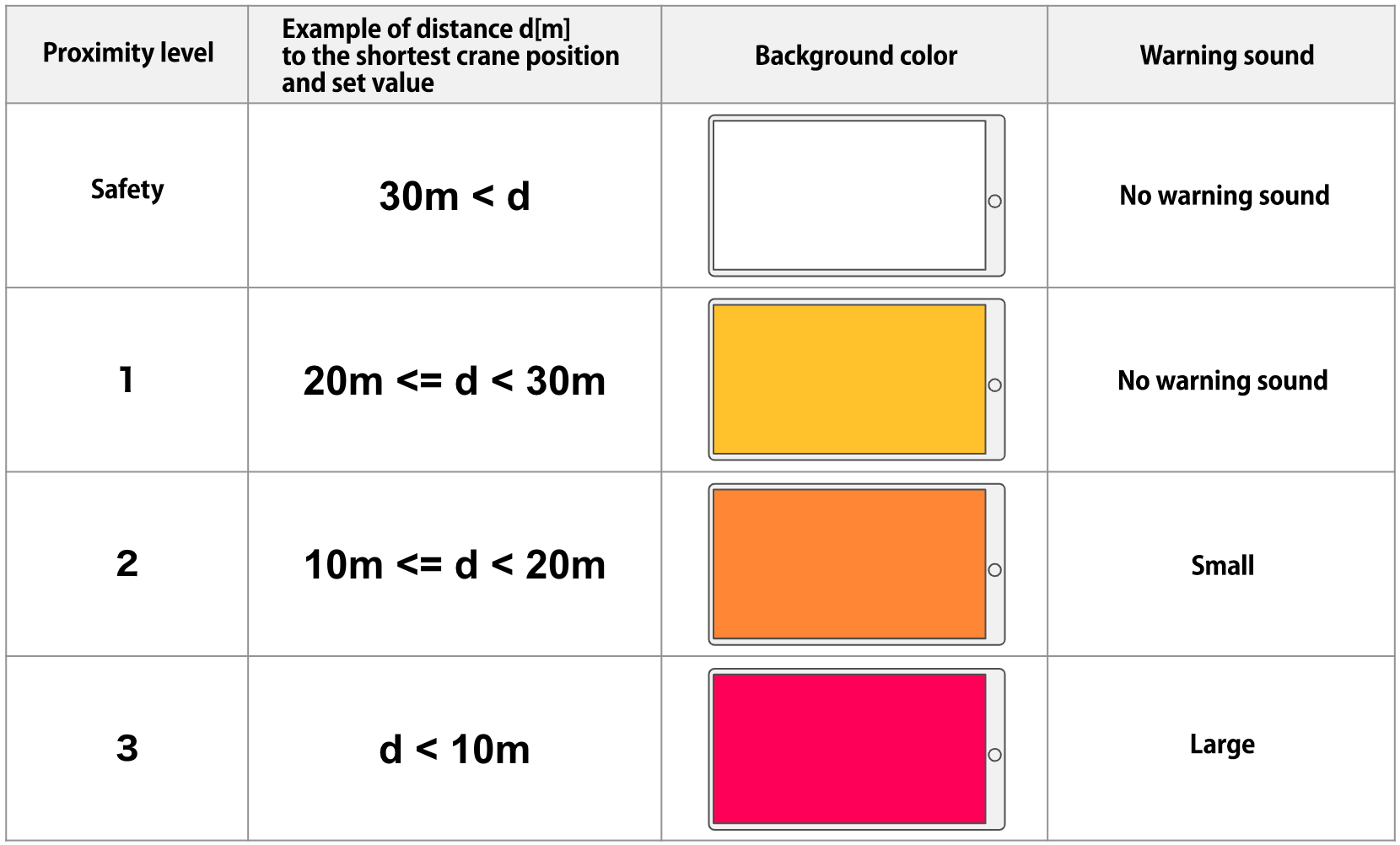
When the distance to the other machine at the shortest position falls below a preset value, an alert is displayed on the screen and a warning tone is sounded. The set values are set in steps as shown in the table below (*The set values in the table below are tentative), and the alert is given in steps according to the distance.
Measurement Accuracy
The following graph shows the X, Y, and Z values measured during a 5-minute period when the position of the GNSS antenna attached to the tip of the jib of a stationary crane was measured by CLAS positioning.
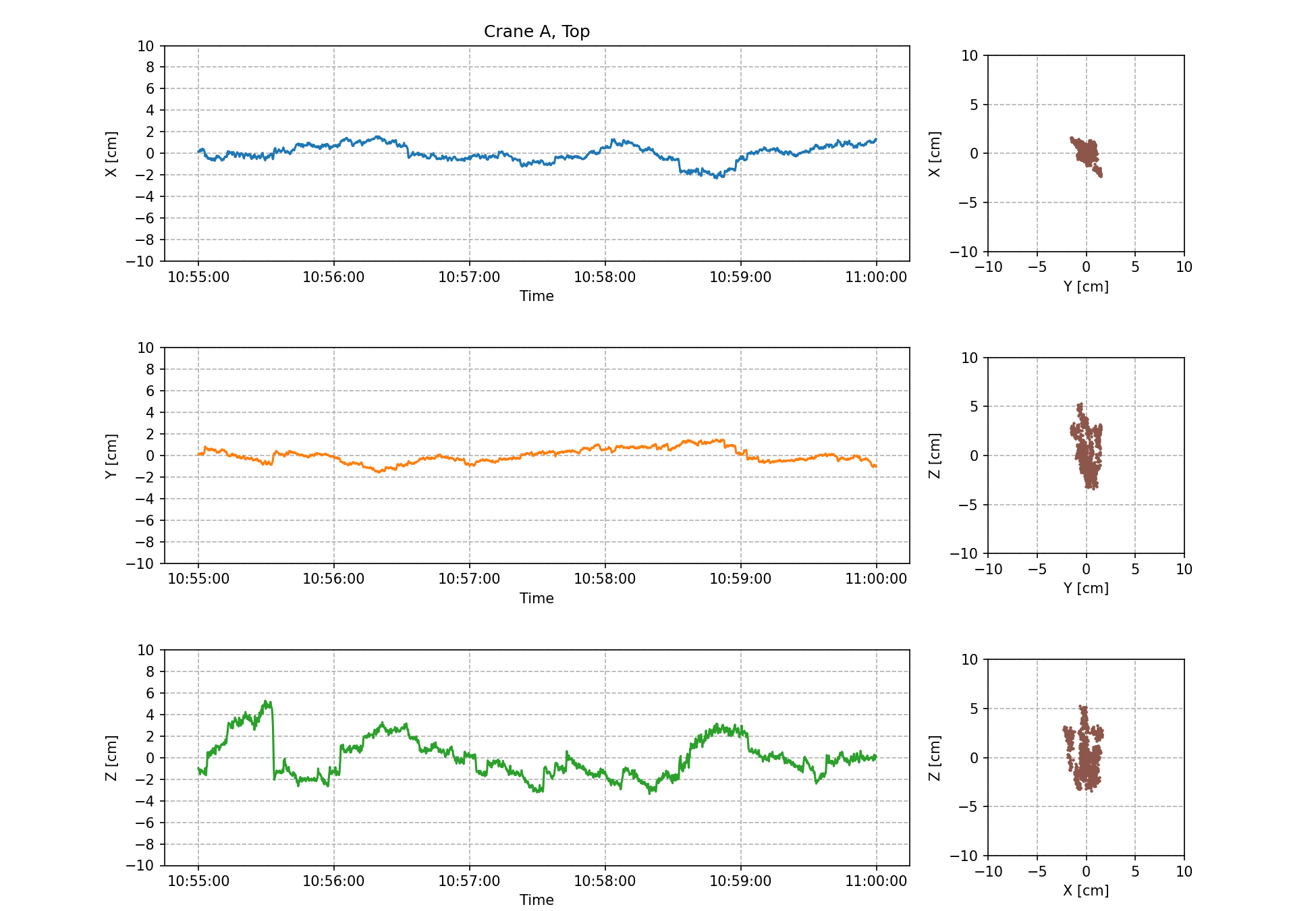
From top to bottom: time-series plot of X-coordinate values and scatter plot of XY-plane, time-series plot of Y-coordinate values and scatter plot of YZ-plane, time-series plot of Z-coordinate values and scatter plot of XZ-plane.
Only samples with good measurement quality (FIX solution) are plotted around the 5-minute average. Units are in centimeters (cm).
The same graph for the same time is shown below for the position of the GNSS antenna mounted on the side of the cabin of a different crane than the crane in the above data.
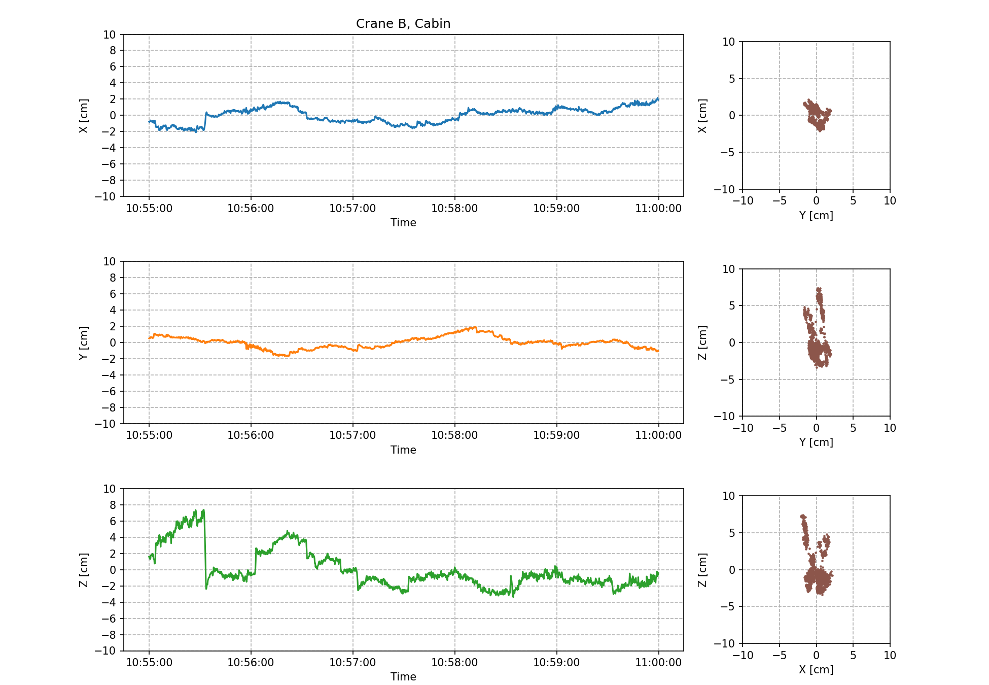
Since both antennas are stationary, the variation is the measurement error. The nominal accuracy of CLAS positioning is 6 cm or less horizontally and 12 cm or less vertically for stationary objects, so the errors are within the expected range.
The common trend seen in both graphs seems to be due to systematic errors inherent to GNSS. Although the systematic error can vary significantly, in the case of this system, the systematic error is offset to some extent because only the relative position of the crane and the crane in the vicinity is used, so the effect of the systematic error seems to be limited.
The FIX rate depends on the environment surrounding the crane, but in an open sky environment, the FIX rate for the antenna at the tip of the jib was generally more than 90.5 %. For the antennas at the side of the cabin, the FIX rate varied between 70% and 90%. The FIX rate from the side of the cabin is lower than that from the tip of the jib because the jib may block some of the GNSS satellites.
Conclusion
The use of CLAS made it possible to realize this system with a simple configuration and without the need for a reference station. The crane itself is large and may not require the same level of accuracy as RTK, making CLAS one of the best examples of its use.
On the other hand, CLAS is limited in the number of available satellites and is sensitive to satellite visibility. Another possible implementation of this system would be to use the Moving Base.
We have applied for a patent for this system jointly with SC Machinery, Inc. Please contact SC Machinery, Inc. for more information about the introduction of this system.
We are developing an IoT system that utilizes GNSS. We can propose the most suitable customization based on your requests. Please feel free to contact us.
Contact
